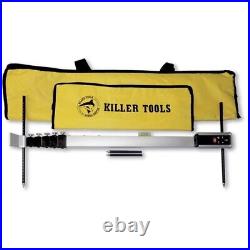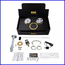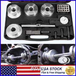
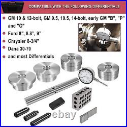
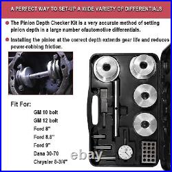
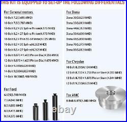
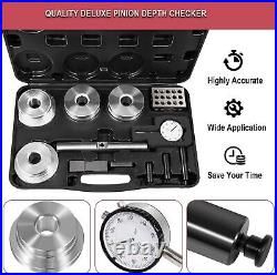
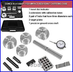
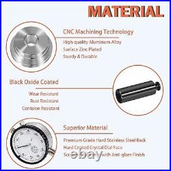
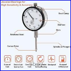

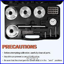
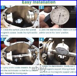
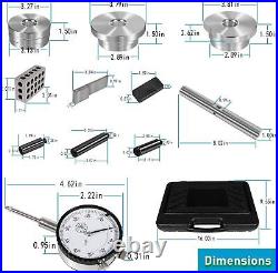
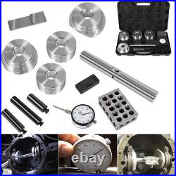
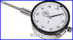

Set up your rearend the right way with a Pinion Depth Checker! This is an indispensable tool whether installing one gearset a year or a dozen. It’s easy to get a perfect tooth contact pattern with a pinion depth checker – far easier than the old trial and error methods. Installing the pinion at the correct depth extends gear life and reduces power-robbing friction. Comes in a handy high-impact resistant carrying case. The pinion depth checker kit is a very accurate method of setting pinion depth in a large number of automotive differentials. Alternative for T&D Machine Products 11001 Deluxe Pinion Depth Checker. Your Best Online Business Partner. Differential Pinion Depth Gauge Checker Tool Kit Fit For GM 10-12 Bolt, Ford 7.5” 8” 8.8” 9”, Dana 30-70, And Most Differentials, Replace For T&D 11001 Pinion Depth Checker. INSTRUCTIONS FOR THE DELUXE PINION DEPTH CHECKER KIT INTRODUCTION. Note: Each of the three included calibration tubes is calibrated and sealed for each application. 1 lmportant: Before attempting calibration, carefully clean all parts. Any dirt can prevent a correct calibration. 2 Insert the Dial lndicator into the Cross Shaft with the Dial lndicator on the rounded side of the shaft and tip extending thru the flat area on the opposite side. Snug the setscrew making sure not to over-tighten. 3 Remove the Indicator Extension stored inside the appropriate Calibration Tube and screw the extension tip into the Dial lndicator until snug. 4 Hold the Cross Shaft and indicator assembly with the indicator tip pointed up. Slip the calibration tube over the tip and allow the tube to rest on the flat area on the cross shaft. 5The thousandth (long arm) pointer should rotate clockwise slightly (about 0.020”) and be pointed approximately straight down, or in the 6 o’clock position. If the pointer does not point straight down, loosen the set screw in the cross shaft and raise or lower the indicator until the needle is pointed straight down with the calibration tube in place. Tighten the setscrew until snug (excessive tightening will lock the indicator shaft or permanently bend the housing) and make sure the pointer remains pointing straight down. NOTE: Be sure that the short pointer (small dial) is in the “zero” position. 6 Loosen the indicator bezel lock screw and with the calibration tube in place, make the final adjustment by rotating the dial face until the zero aligns with the pointer. Tighten the indicator bezel lock screw. Your Pinion Depth Checker is now set and calibrated for a depth of exactly 3.375″(Or 1.900″ for the Ford 9″ or 2.500″ for the intermediate differentials). This is the CALIBRATED DEPTH. 1 Carefully remove any sharp edges or burrs from the carrier bearing housing and caps to avoid any inaccuracy or marring of the hubs. 2 Make note of the pinion depth inscribed on your pinion gear. If your pinion does not have a depth number on it, go to the “OEM GEAR APPLICATIONS” Section to find the pinion depth. 3 Place the pinion in the case with the appropriate bearings and shims. 4Clean the appropriate Target Plate and the face of the pinion gear and then place the Target Plate on the face on the pinion. 5 Select the appropriate hubs and lightly oil the bores to prevent galling and carefully insert the Cross Shaft into the Hubs. Place this assembly in the case and tighten main cap bolts to 25 ft. See picture for Hub Applications. NOTE: The “A” diameter has a machined flat to clear the pinion support in Ford 9 rear ends. Additional relief may be needed for individual applications. When using the “A” diameter in Dana 60s, the machined flat should be positioned at 90 degrees to the cap parting line. 6 Slide the Indicator and Cross Shaft as close as possible to pinion gear, minimizing any overhang of theTarget Plate. Be sure to retract the indicator plunger shaft just enough to clear the Target Plate to prevent bending the indicator. 7 Make sure the Indicator shaft end is seated on the target plate and note the reading on the dial. Multiply the small counter number by 0.100 and add the thousandths pointer reading to get your INDICATOR READING. Subtract your lNDICATOR READING from the CALIBRATED DEPTH (3.375 for the long calibration tube, 2.500 for the intermediate, and 1.900 for the short) and you will have obtained your MEASURED PINION DEPTH. Example: lf the reading on the indicator were 0.778″ (seven complete revolutions plus reading), subtracting from 3.375 would equal 2.597″. This is the MEASURED PINION DEPTH. NOTE: To minimize error, rotate the pinion gear to at least four different positions and average the three most similar readings. 8 Compare the MEASURED PINION DEPTH to the Pinion Depth number inscribed on the pinion gear or obtained from the OEM Gear Section to determine the amount of shims to be added or removed. The list provided on this page will extend the capabilities of your PiNION DEPTH CHECKER KIT. The method described below will allow you to set up differentials with gears not inscribed with a pinion depth, as is the case with OEM factory gears. 1 Measure the PINION HEAD THICKNESS (PHT) with a micrometer. This thickness is defined as the dimension from the top of the pinion gear to the thrust bearing mounting surface. 2 Find the correct application listed below and note the MASTER HOUSING DIMENSION (MHD). 3 Subtract the (PHT) from the (MHD). The number obtained is the PINION DEPTH (PD). 4 Now, you can set up your differential as described in the section “MEASURING PINION DEPTH”. 10-Bolt 7.2 (3.693 MHD), 10-Bolt 7.5 (3.787 MHD), 10-Bolt 8.2 × 25 Spline Pinion (4.175 MHD), 10-Bolt 8.2 × 27 Spline Pinion (4.175 MHD), 10-Bolt 8.2 x Thin 55-64 Vette (4.125 MHD), 10-Bolt 8.5 × 30 Spline (4.262 MHD), 10-Bolt 8.5 × 27 Spline (4.262 MHD). 12-Bolt 8.875× 1.438 Pinion Dia. (4.556 MHD), 12-Bolt 8.875 × 1.625 Pinion Dia. (4.670 MHD), 12-Bolt 9.300 (4.620 MHD), 14-Bolt 9.500(4.865 MHD), 14-Bolt 10.500 (5.400 MHD). 10 Bolt 8.250 (4.124 MHD), 12 Bolt 8.750× 1.750 Pinion Stem (4.350 MHD), 12 Bolt 8.750 × 1.875 Pinion Stem (4.344 MHD), 12 Bolt 9.250 (4.625 MHD). 6.625 (3.500 MHD), 7.5 (4.040 MHD), 8.0 (4.000 MHD), 8.8 (4.415 MHD), 9.0 (4.375 MHD). Dana 30 (3.625 MHD), Dana 35 (3.813 MHD), Dana 44 (4.312 MHD), Dana 50 (4.630 MHD), Dana 60 (5.000 MHD), Dana 70 (5.375 MHD), Dana 80 (5.812 MHD). Deluxe Pinion Depth Gauge Checker Tools. For GM 10 bolt 12 bolt, Dana 30-70, Ford 8.0”, 8.8”, 9.0′. Single item or Set. If you need return, please contact our customer service representative, let us know the detailed problem and send us some pictures for confirmation. Thank you for your understanding. Our office hours is as below. 9:00 a. To 6:00 p. (GMT +8) of Monday to Friday – 9:00 a. To 1:00 p. (GMT +8) of Saturday And our office is closed on Sunday and public holidays. We apologize for the late reply during the holidays. Car & Truck Tools. Car & Truck Parts Accessories. Performance & Racing Parts. U-Cup Seal for SEARS Floor Jack 328 Series 22 x40 x12mm 328.12001, 328.12002 etc. Oil Filter Wrench Cap For Toyota Prius Corrola Rav4 Tool Remover 14 Flutes 64mm. 64mm 14 Flutes Oil Filter Cap Wrench Remover Tool for Toyota Lexus 2.5L-5.7L. Shifter Seal Remover Installer Tool for GM TURBO 300 350 400 425 475 700-R4 4L60. For Cummins ISX QSX ISX15 Front Rear Crankshaft Seal Remover Installer Tools Kit. For Dometic / Sealand 385230335 Toilet Vacuum Breaker Kit With Diverter Valve. A74905BK Hi-Performance Servo Kit for Corvette TH700R4 4L60E 4L65E 2-4 Band 1982. 660040-1 Impeller Puller Removal for Impellers 2-1/4″ to 2-9/16″ Jabsco Pump.

